Smart Devices
Robots use Smart Devices to interact with the environment through sensing or actuation. Currently, each Smart Device (SD) consists of an Arduino Micro mounted on a custom printed circuit board. A Raspberry Pi 4 Model B, the kit’s central single-board computer (SBC), communicates with the Arduinos over USB serial.
Historically, PiE manufactured custom cables and boards to support real-time communication and flexible configuration. However, custom hardware hampered debugging and development, and the kit’s SBC at the time, the Beaglebone Black (BBB), did not provide real-time guarantees anyway. As a result, the kit shifted towards cheap commodity hardware like Arduino and USB, which are well-tested, enjoy widespread software support, and are relatively simple.
During the spring 2017 season, PiE considered using USB HID, used for peripherals like keyboards and mice, to circumvent the BBB’s hardware limit on the number of USB CDC devices. However, the HID abstraction proved too difficult to use. A USB OTG hack for chaining USB hubs was required to raise the limit of six devices.
Protocol Specification
The Smart Device Protocol is a duplex packet-based protocol layered on a reliable transport like USB serial for communication between an SBC running Runtime and a Smart Device. PiE chose a packet-based protocol to support heterogenous and relatively low-frequency messages (for example, an update about every 50 ms).
Each Smart Device has between zero and 16 (inclusive) parameters:
Each parameter has a unique unsigned 8-bit integer identifier, incrementing from zero. An
N-parameter device has parameters with IDs0, 1, 2, ..., N-1.Each parameter has a unique human-readable name. There are no formal restrictions, but snake case names are preferred.
Each parameter is either read-only, write-only, or readable and writeable.
Each parameter has a data type. Similar to standard C types, the supported types are:
bool(1 byte)uint8_tint8_tuint16_t
int16_tuint32_tint32_tuint64_t
int64_tfloat(4 bytes)double(8 bytes)
As implied by its name, an
(u)intNN_tintegral type is exactlyNN/8bytes wide. Theuprefix denotes an unsigned type. An integral type without theuprefix is signed.
Warning
For some boards, Arduino’s double type is as wide as its float type: 4 bytes.
Avoid adding parameters with the double type unless the Smart Device’s microcontroller actually produces doubles eight bytes wide, as required.
Message Format
Every message (packet) follows a basic format:
Message Format
The message ID is an unsigned 8-bit integer, which specifies the message’s type and determines the payload format.
The payload length is an 8-bit unsigned integer specifying the number of bytes in the payload. The payload can be up to 255 bytes long (inclusive).
The checksum is the XOR of every other byte in the message (the portion shown in blue).
UID Format
Each Smart Device is assigned a unique 88-bit identifier (UID) at compile time:
UID Format
The device ID is an unsigned 8-bit integer, which specifies the device’s type.
The year is an unsigned 8-bit integer specifying what competition the device was manufactured for. Year
0x00corresponds to the spring 2016 season, and each subsequent season increments the year ID. (Although PiE strives to hold a competition annually, the year ID would not increment in a year where PiE is unable to.)The random portion of the UID is randomly generated to ensure UID uniqueness. In any given year, the probability of a collision with 1000 of one type of device is roughly 0.05%. This is a generous upperbound on the actual collision likelihood, since PiE typically produces many times fewer of even the most common device, motor controllers.
Message Types
ID |
Name |
Direction |
Description |
|---|---|---|---|
|
Ping |
SBC → SD |
The SBC pings the SD for enumeration purposes. The SD responds with a subscription response. |
|
Subscription Request |
SBC → SD |
The SBC requests data to be returned asynchronously at a given constant interval (delay) for some parameters. The SD responds with a subscription response.
|
|
Subscription Response |
SBC ← SD |
The SD acknowledges a subscription with its subscription status and UID.
|
|
Device Read |
SBC → SD |
The SBC requests some values from the SD. The SD responds with zero or more device data packets with values for all readable parameters requested. |
|
Device Write |
SBC → SD |
The SBC attempts to write some values to the SD. The SD responds with zero or more device data packets describing all the readable parameters that were successfully written to. There is no acknowledgement for write-only parameters. |
|
Device Data |
SBC ← SD |
The SD sends values of readable parameters to the SBC. This can occur in response to a device read/write or as part of a subscription update. |
|
Device Disable |
SBC → SD |
The SBC attempts to disable the SD, which ceases all operation for safety reasons. The SD continues to respond to packets and may resume operation without power cycling. |
|
Heartbeat Request |
SBC ↔ SD |
Either the SBC or the SD requests the other endpoint to send a heartbeat response, which should be sent back immediately. The payload (ID) is currently unused, but may be used for tracking outstanding requests to measure latency. |
|
Heartbeat Response |
SBC ↔ SD |
The endpoint receiving a heartbeat request should send back a heartbeat response with the request’s ID. |
|
Error |
SBC ← SD |
The SD indicates to the SBC an error has occurred. |
Note
To avoid chatter, subscriptions are generally preferred over device reads (polling) for regular updates. The delay between updates is also likely to be more consistent.
The payload format of each message type is shown below. The endianness of each multi-byte segment is determined by the endianness of the particular board. Arduino Micros are little-endian (least significant byte first).
Payload Formats
Some payloads begin with a
Paramsbitmap to reference a subset of the device’s parameters. The parameter with IDiis included if and only if bitiis one, with the bitmap’s least significant bit defined as the 0th bit.The
Delayfield of subscription request/response packets is an unsigned 8-bit integer specifying the number of milliseconds between updates.Device write and device data packets order values by ascending parameter ID. The sum of the widths of the included parameters’ types must equal the length of the values segment.
The Smart Device Protocol is asynchronous, meaning messages may be interspersed in whatever order either endpoint chooses. For example, it is valid for an endpoint to have two in-flight heartbeat requests. The endpoint need not block sending the second heartbeat request until the first heartbeat response returns.
A Smart Device may disable itself for safety reasons if it does not receive a valid packet from the SBC after some time.
Error Code |
Description |
|---|---|
|
Unexpected packet delimiter |
|
Checksum error |
|
Generic error |
Transport
When the Smart Device Protocol is layered on a bytestream-based transport like USB serial, the communication endpoints must delimit packet boundaries with a null byte (0x00) and encode each packet with Consistent Overhead Byte Stuffing (COBS) before placement on the wire.
At the cost of slightly expanding each message (proportional to the message’s length), COBS ensures encoded messages are free of the null byte.
This encoding allows the bytestream to transport variable-length messages without requiring endpoints to maintain packet length state.
Device List
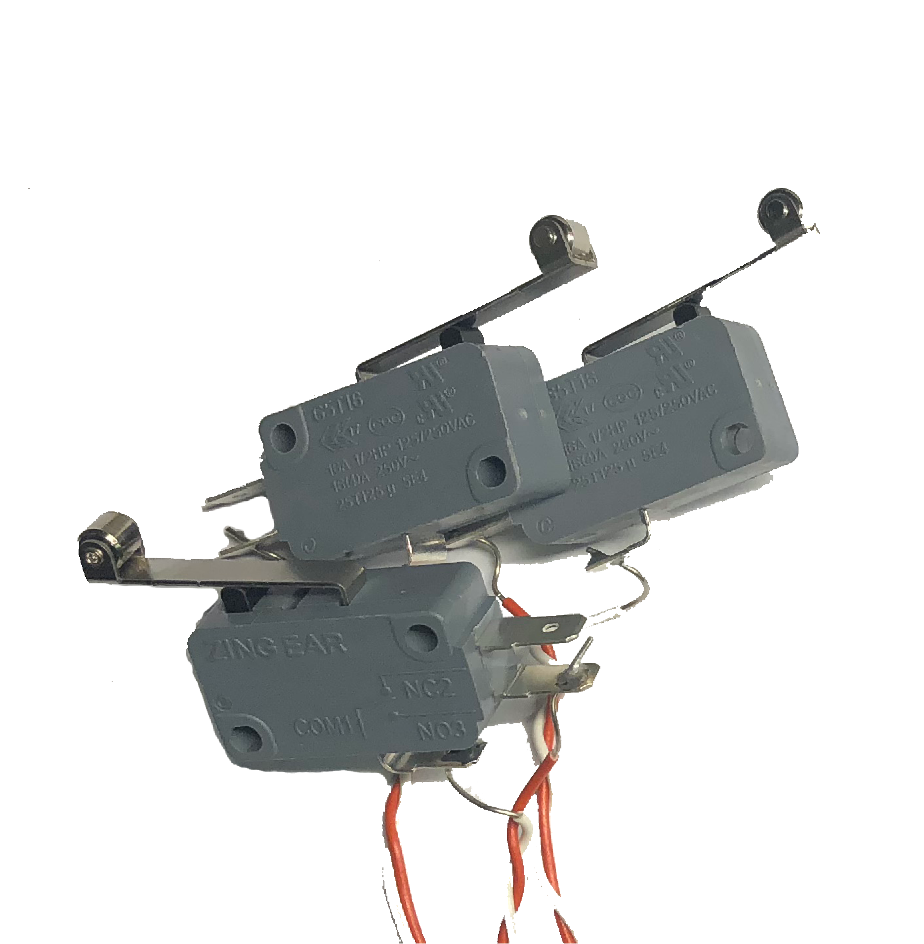
LimitSwitch(ID:0x00)Detects whether three switches are open or closed. The switches are open, by default.
Limit Switch Board and Switches¶ 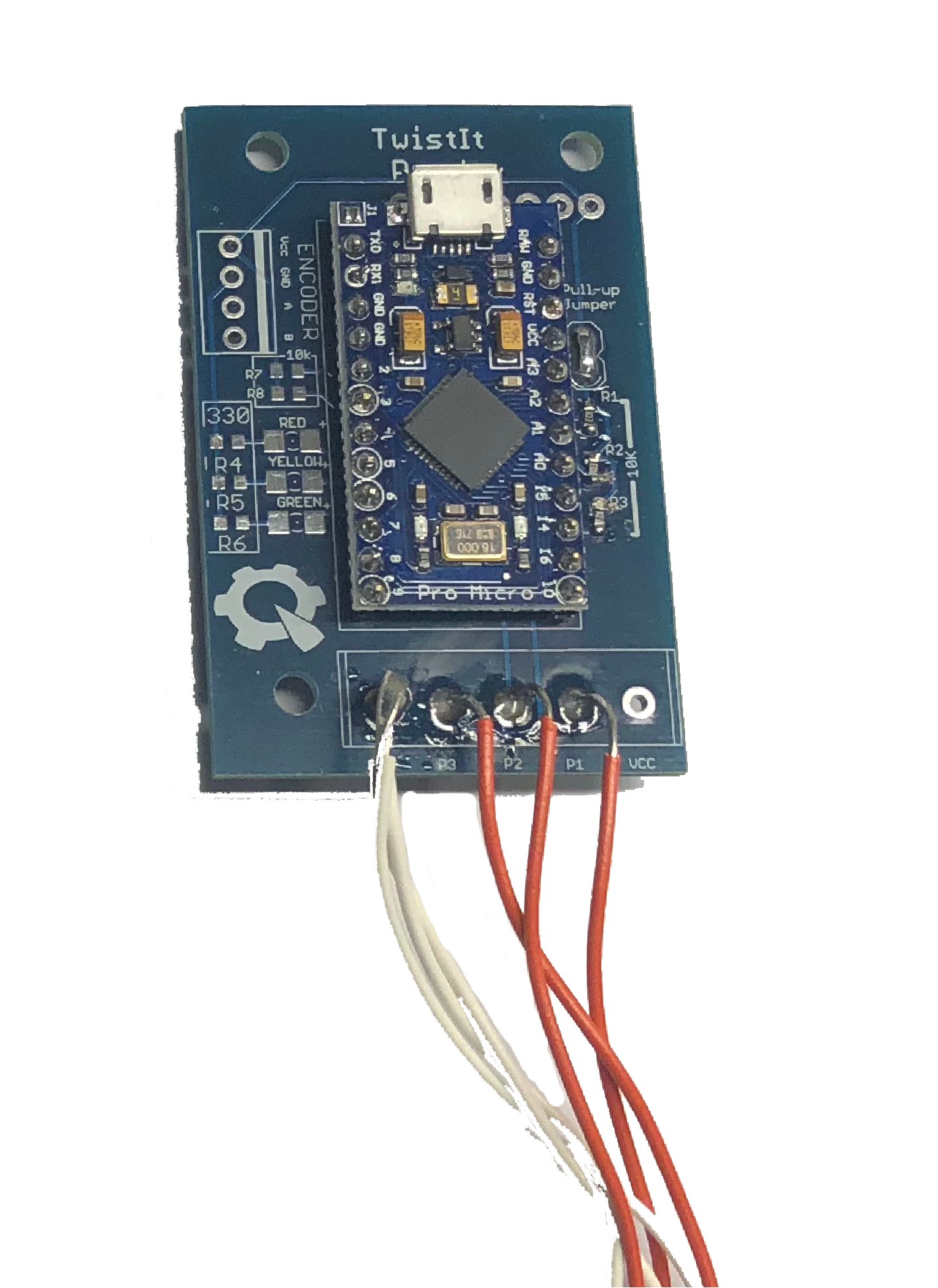
Parameter Information¶ ID
Name
Type
Read?
Write?
Notes
0x0switch0boolYes
No
True when a switch is closed.
0x1switch1boolYes
No
0x2switch2boolYes
No
LineFollower(ID:0x01)Three colinear brightness sensors used to detect and follow reflective tape on the floor. The line follower works best when the sensors are as close to the ground as possible.
Line Follower Board and Head¶ 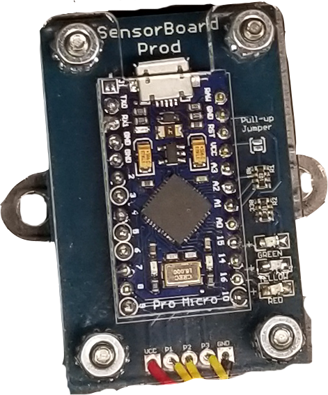

Parameter Information¶ ID
Name
Type
Read?
Write?
Notes
0x0leftfloatYes
No
Intensities are between 0 and 1, where 0 denotes complete darkness and 1 denotes complete reflection.
0x1centerfloatYes
No
0x2rightfloatYes
No
Potentiometer(ID:0x02)Detects the angle of three rotating dials. The track spans only a circular sector, not the full disk.
Parameter Information¶ ID
Name
Type
Read?
Write?
Notes
0x0pot0floatYes
No
Rotations are between 0 and 1, which correspond to the two ends of the sector.
0x1pot1floatYes
No
0x2pot2floatYes
No
Encoder(ID:0x03)Detects angular position like the potentiometer, but for a continuously rotating joint.
Parameter Information¶ ID
Name
Type
Read?
Write?
Notes
0x0rotationfloatYes
No
A position in encoder ticks (4400 per revolution).
BatteryBuzzer(ID:0x04)Monitors battery voltages and cell balances. The power distribution board (PDB) is shown below (left):
Closing the circuitbreaker’s yellow switch in the center switches on the PDB. Pressing the circuitbreaker’s red button opens the switch.
Horizontal Anderson connectors, which power motors, populate the PDB’s right side. Following convention, the black connectors stand for ground, the red for power. The motors use vertically stacked Andersons that can only be plugged into a motor controller, not directly into the PDB, to discourage such an accident.
ATX connectors, which power servos and the Raspberry Pi, populate the PDB’s left side.
The buzzer in the bottom left corner beeps once when switched on under normal operation, and beeps continuously when the battery condition is unsafe.
The ATX connectors above the buzzer connect to the battery.
The seven-segment display in the bottom right corner shows the battery’s voltage.
The Arduino is optional. The buzzer works even without the Arduino.
The LIPO battery (shown below, right) contains three separate cells with their own voltages that are connected in parallel. Using a battery under unsafe conditions may permanently damage the battery and pose an electrical or fire risk. Generally, an acceptable battery voltage ranges from about 10.5V to 12V. Avoid overcharging batteries by leaving them unsupervised for more than several hours.
Power Distribution Board and Battery¶ 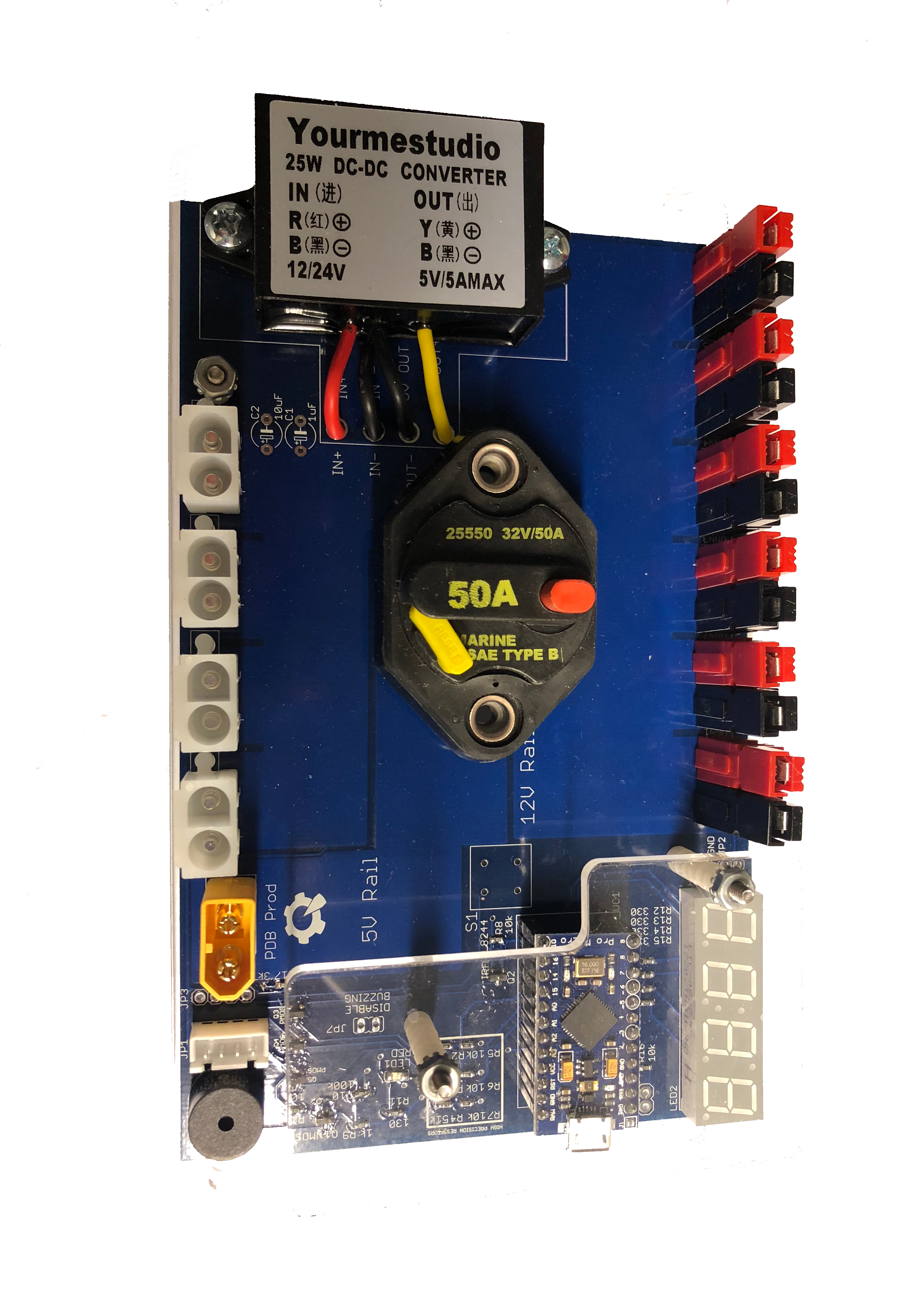

Parameter Information¶ ID
Name
Type
Read?
Write?
Notes
0x0is_unsafeboolYes
No
True when the battery voltage is too low or the cells are too imbalanced for safe use.
0x1calibratedboolYes
No
True if the battery has been calibrated (calibration voltage is stored in EEPROM).
0x2v_cell1floatYes
No
Voltages (in Volts) of each of the three cells.
0x3v_cell2floatYes
No
0x4v_cell3floatYes
No
0x5v_battfloatYes
No
The overall battery voltage (in Volts). Alias for
v_cell3.0x6dv_cell2floatYes
No
v_cell2minusv_cell1.0x7dv_cell3floatYes
No
v_cell3minusv_cell2.TeamFlag(ID:0x05)Powers colored LEDs to indicate the robot’s team.
Team Flag¶ 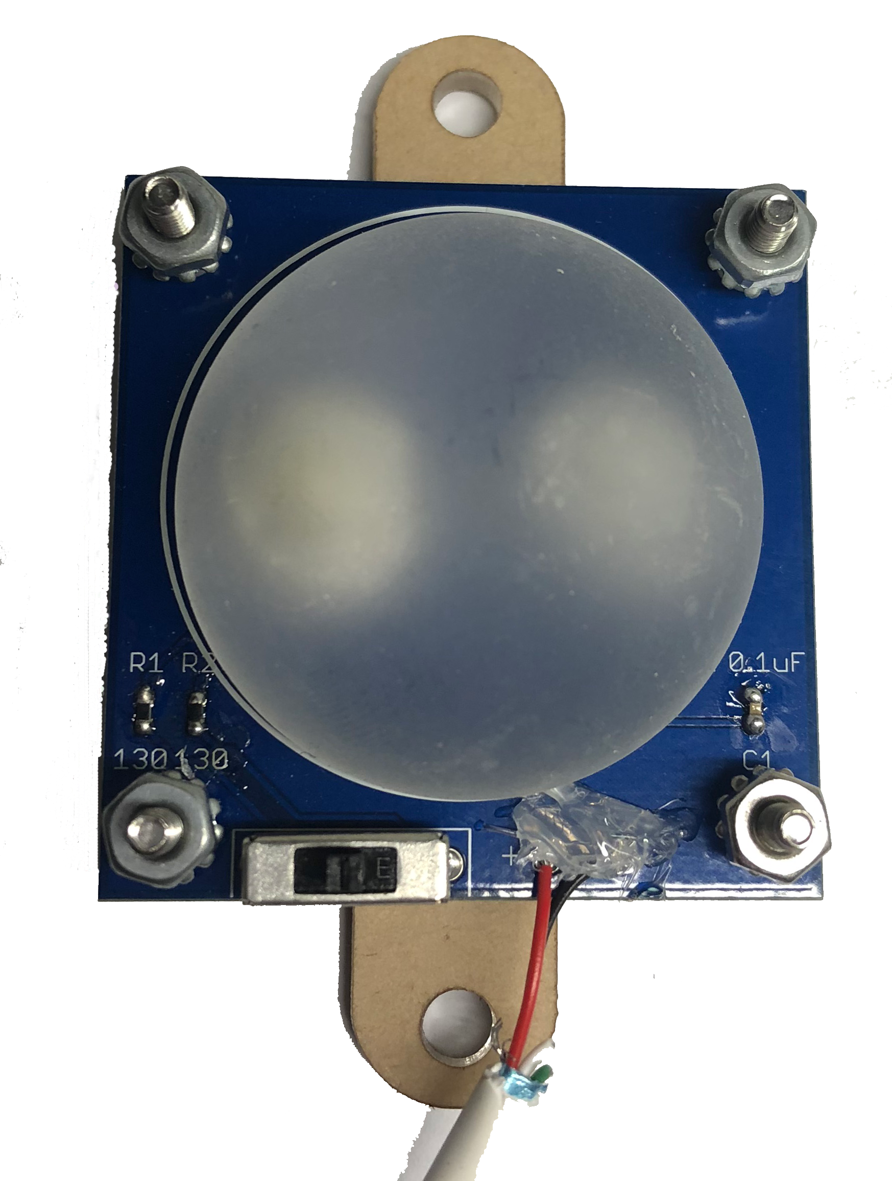
Parameter Information¶ ID
Name
Type
Read?
Write?
Notes
0x0modeboolYes
Yes
True if all LEDs are enabled (not necessarily on).
0x1blueboolYes
Yes
True if the LED color is enabeld. Technically, these flags allow both colors to be enabled simultaneously.
0x2yellowboolYes
Yes
0x3led1boolYes
Yes
Each color can light up to four individual LEDs to allow for varying degrees of brightness. These parameters are true if the corresponding LEDs are active.
0x4led2boolYes
Yes
0x5led3boolYes
Yes
0x6led4boolYes
Yes
Grizzly(ID:0x06)The discontinued Grizzly Bear motor controller. No parameters are specified, but the device ID is reserved for future use.
ServoControl(ID:0x07)Controls a pair of servo motors, which do not spin continuously and are best used for joints.
Servo Controller and Servo Motor¶ 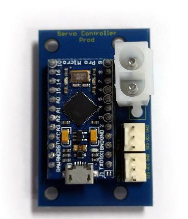

Parameter Information¶ ID
Name
Type
Read?
Write?
Notes
0x0servo0floatYes
Yes
A position between -1 and 1.
0x1servo1floatYes
Yes
LinearActuator(ID:0x08)An extensible joint creating translational motion. No such device exists yet, but the device ID is reserved for future use.
ColorSensor(ID:0x09)Color sensor. No such device exists yet, but the device ID is reserved for future use.
YogiBear(ID:0x0A)A discontinued COTS motor controller. It has the same behavior and parameters as the
PolarBear(see below).RFID(ID:0x0B)Detects radio-frequency identifiers. Because of hardware quirks, this sensor can sometimes be slow or report false negatives. The RFID sensor also works best at very close range (0.5 inches is about the maximum range).
RFID Reader¶ 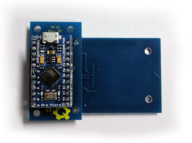
Parameter Information¶ ID
Name
Type
Read?
Write?
Notes
0x0iduint32_tYes
No
The identifier. If
detect_tagis false, this parameter is undefined.0x1detect_tagboolYes
No
True if a tag is detected.
PolarBear(ID:0x0C)The COTS motor controller that succeeded the Yogi Bear. If equipped with a position encoder, the Polar Bear can supposedly perform PID to track position and velocity setpoints. It has a unique safety feature: it disables itself if Runtime does not respond to the Polar Bear’s heartbeat requests.
Polar Bear and DC Motor¶ 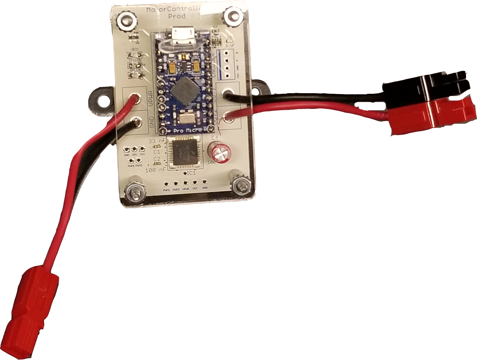

Parameter Information¶ ID
Name
Type
Read?
Write?
Notes
0x0duty_cyclefloatYes
Yes
Between -1 and 1. The sign indicates the direction the motor should run in, and a greater duty cycle magnitude corresponds to a faster speed (more current).
0x1pid_pos_setpointfloatNo
Yes
A position in encoder ticks. There are 4400 ticks per revolution, and the sensor has a resolution of a 100 ticks. That is, the motor can rotate by up to 100 ticks per read cycle.
0x2pid_pos_kpfloatNo
Yes
The PID coefficients for position tracking. Defaults to 1 for the proportional term and 0 for the others.
0x3pid_pos_kifloatNo
Yes
0x4pid_pos_kdfloatNo
Yes
0x5pid_vel_setpointfloatNo
Yes
A velocity (encoder ticks per second).
0x6pid_vel_kpfloatNo
Yes
The PID coefficients for velocity tracking. Defaults to 1 for the proportional term and 0 for the others.
0x7pid_vel_kifloatNo
Yes
0x8pid_vel_kdfloatNo
Yes
0x9current_threshfloatNo
Yes
Current threshold in Amperes. The hardware also enforces a current limit.
0xAenc_posfloatYes
Yes
Encoder position in ticks.
0xBenc_velfloatYes
No
Encoder velocity in ticks per second.
0xCmotor_currentfloatYes
No
Motor current usage in Amperes.
0xDdeadbandfloatYes
Yes
Deadband between 0 and 1. Duty cycles with a magnitude less than the deadband will not activate the motor.
DistanceSensor(ID:0x10)Detects distance using a technology like LIDAR or ultrasound. No such device exists yet, but the device ID is reserved for future use.
MetalDetector(ID:0x11)Detects the metals. No such device exists yet, but the device ID is reserved for future use.